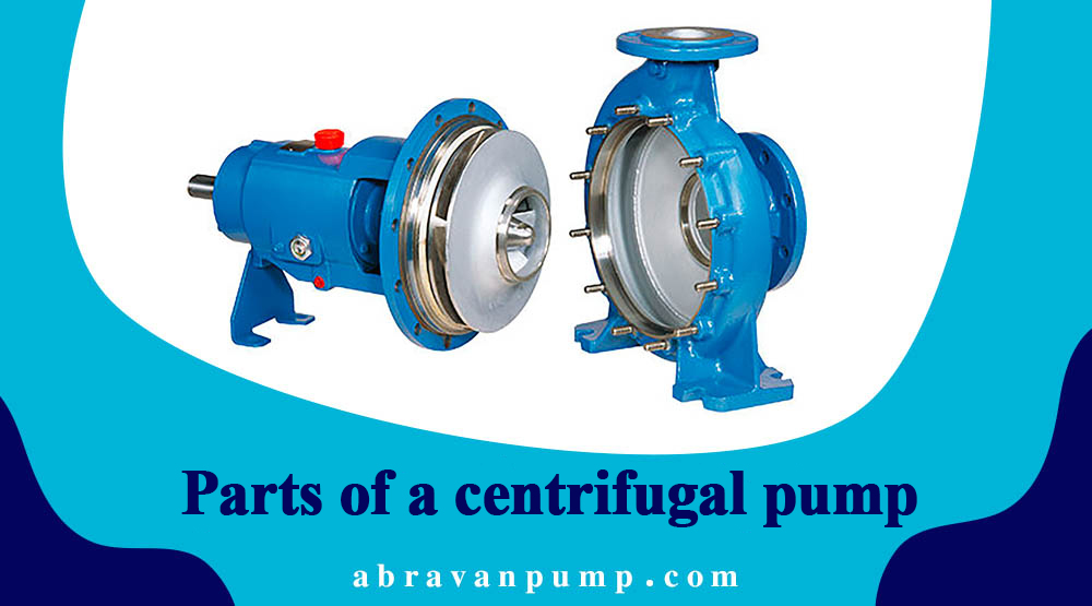
The main part of a centrifugal pump includes an impeller or rotor. This impeller consists of 6-12 blades, symmetrically arranged on the impeller. The curvature of the blades is opposite to the rotation of the impeller, as shown in the figure below.

The covering that surrounds the impeller is called a volute casing. The volute casing is related to the suction and discharge pipes.
Before getting acquainted with the components of a centrifugal pump, it is better to understand how this industrial pump operates. At the suction pipe inlet, a one-way valve and a filter are installed to allow the fluid to enter. Before the centrifugal pump starts, both the suction pipe and the pump are filled with fluid, so the inlet valve of the suction pipe is closed. When the pump is activated by a motor, centrifugal force is created inside the impeller, causing the fluid to be pushed between the impeller blades towards the volute casing. From there, it is directed towards the discharge pipe.
Therefore, inside the pump and the suction pipe simultaneously, negative pressure is created. As a result, the inlet valve of the suction pipe opens, and after passing through the suction pipe, the fluid, under the external pressure p° acting on the free surface of the fluid in the lower reservoir, enters the pump. In this way, the continuous rotation of the impeller inside the pump causes the continuous flow of the fluid and enables the fluid to be transferred from one source (lower reservoir) to another destination (upper reservoir). The impellers of the pumps can be designed in various forms such as open, semi-open, and closed, as shown in the figure below.

The structure of a centrifugal pump:
In centrifugal pumps, water is expelled from the center with high-speed impeller blades. Therefore, before water enters the discharge pipe, some of its kinetic energy needs to be converted into pressure energy. To achieve this, a device is provided in these machines that gradually reduces the speed of water without creating turbulence or rotational flow patterns, decreasing the water velocity and progressively increasing the potential energy. This process elevates the manometric head of the pump in meters and increases its efficiency.
In the initial types of centrifugal pumps, water directly enters the circular collecting chamber with relatively high speed and is then directed towards the discharge pipe. The fluid’s velocity in the collecting chamber continuously increases from a section near the discharge pipe to a section just before reaching the discharge pipe. Consequently, all the kinetic energy of the water’s velocity is wasted as turbulence and rotational flows inside the chamber when it exits the impeller. To prevent this energy loss and facilitate the conversion of kinetic energy into pressure energy, a volute casing is constructed, or ring-shaped guide vanes (diffusers) are placed as shown in the figure.

The volute casing, as a covering, surrounds the impeller and guides the outgoing water towards the discharge pipe. The construction of this casing is designed in a way that its cross-sectional area uniformly and gradually increases. Consequently, the water flow speed inside this casing, which is peripheral, gradually decreases, and conversely, the fluid pressure gradually increases. In this manner, the presence of the volute casing reduces kinetic energy and increases potential energy.
Practically, the efficiency of the volute casing is low, around 10%. Therefore, the efficiency factor of the volute casing is only slightly higher than that of the circular casing. Another method to convert the kinetic energy of the outgoing fluid into potential energy in a centrifugal pump is by passing the outgoing water from the impeller through stationary blades that act as diffusers. This means that their cross-sectional area increases in the direction of flow (converging or diverging) and as a result, the outgoing flow velocity gradually decreases, and conversely, the fluid pressure increases. The presence of guide vanes in turbines operates in contrast to pumps. In turbines, the presence of guide vanes increases kinetic energy and reduces potential energy. Therefore, the water entering the impeller will have high-speed and the correct direction.
Pumps equipped with guide vanes are called turbine pumps. In fact, the pump acts like a reversed turbine and in practice, in necessary cases, machines like these are used both as a turbine and as a pump. Therefore, by placing guide vanes between the volute casing and the impeller, it is possible to prevent movement instability and heavy losses caused by turbulence to a large extent, converting kinetic energy into potential energy.